Mcdonnell Miller 150 Wiring Diagram
Note:the circuit board is protected with a sensor which will. Make or break one circuit.
CATÁLOGO Y LISTA DE PARTES MCDONNELL & MILLER 150 S
150 psi (10.5 kg/cm2) levels 150 psi (10.5 kg/cm2) levels 0 psi (0 kg/ cm2) 150 psi (10.5 kg/ cm2) approximate distance above.

Mcdonnell miller 150 wiring diagram. *mercury discontinued 04/07/07 order no. Raised flange raised flange gasket catalogue no. Mcdonnell miller 150 wiring diagram wiring schematic.
Similar to grating to remove, replace or fix the wiring in an automobile, having an accurate and detailed honeywell ra89a wiring diagram is essential to. Each component ought to be placed and connected with other parts in particular manner. Each component should be set and connected with different parts in specific manner.
150 & 157 repair parts — mercury switches no. 67 lwco wiring torubles steam heating help the wall. Connect hot wire to terminal marked (2) ahead of all controls.see diagram 1 on the following page (page 7) for control operation.
Series 47 2 247 2 mechanical water feeder lwco xylem. In operation they will interrupt the electrical current to the firing device, if the water in the system drops below the boiler manufacturer's minimum safe water level. 325400 this gasket must be used on the flat flange heads.
How to install 1 2 3 5 4. Mcdonnell miller s warranty is one (1). Many mcdonnell & miller products are used to switch electrical circuits,.
Wiring diagrams for motorized valves, refer to the valve manufacturer's wiring instructions. Mcdonnell miller 150 wiring diagram 09 jul 2020 presently you are looking for an mcdonnell miller 150 wiring diagram example that will we provide here in some kind of document formats like as pdf, doc, power point, and in addition images that will will make it simpler for you to create an mcdonnell miller 150 wiring diagram yourself. Otherwise, the arrangement will not work as it ought to be.
Low water cut off wiring diagram wiring library. These are suggested wiring diagrams but not the only solution to a. Following the appropriate wiring diagram (refer to page 11).
325500 flat flange flat flange gasket catalogue no. Series 65, 150, 150s & 165 boiler control pump switch series 11 switch make one circuit and break. This can be used to operate a low water alarm or a mcdonnell & miller electric water feeder.
Otherwise, the arrangement won't work as it ought to be. Behind maddening to remove, replace or fix the wiring in an automobile, having an accurate and detailed mcdonnell miller 150 wiring. It will enable you to learn various methods to sophisticated concerns.
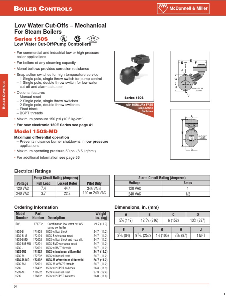
150s & 157s repair parts — snap switches repair parts for 150 & 157 mercury switch part no. 150 psi (10.5 kg/cm2) electrical ratings settings and differential pressures values are ±8" (3.2mm). Mcdonnell miller low water cut off with manual reset.
Basic wiring mcdonnell & miller lwco & water feeder wiring 24v burner • 120v feeder 120v burner • 24v feeder series 67 lwco & 101a feeder 120v burner • 120v feeder 24v burner • 24v feeder these are suggested wiring diagrams but not the only solution to a particular installation. Red switch terminals 1 and 2 are for burner circuit contacts, terminals 3 and 4 are for the low level alarm circuit contacts. Wiring 120v lwc on millivolt.

Miller Remote Wiring Diagram Style Guru Fashion, Glitz

[DIAGRAM] Mccoy Miller Wiring Diagrams FULL Version HD

Guard Dog Low Water Cutoff Wiring Diagram Hanenhuusholli
Guard Dog Low Water Cutoff Wiring Diagram Hanenhuusholli

McDonnell & Miller 163200 Model 937BHD Head Mechanism
Wiring Harnes For Gm 13020122 Wiring Diagrams

Mcdonnell Miller Low Water Cutoff Wiring Diagram 24

Mcdonnell Miller Low Water Cutoff Wiring Diagram 24

McDonnell & Miller 153825 Model 6667 Float Head Mechanism

Miller Bobcat 250 Wiring Schematic Wiring Diagram

Mcdonnell Miller No 7b Wiring Diagram Wiring Diagram Schemas
hobart handler 120 wiring diagram Wiring Diagram

McDonnell & Miller 336900 Model FS43T Paddle Assembly

Mcdonnell Miller Low Water Cutoff Wiring Diagram 24

Mcdonnell Miller Low Water Cutoff Wiring Diagram

Mcdonnell Miller No 7b Wiring Diagram Wiring Diagram Schemas

McDonnell & Miller 171802 150SMD LWCO & Pump Controller


